I designed and built a low-cost CNC plotting machine using an Arduino UNO-based control system. The machine converts digital designs into physical drawings by interpreting G-code and controlling stepper motors for precise X and Y axis motion.
Later I extended it with an ESP32 IoT layer for wireless G-code transmission, browser-based control, and live machine status monitoring — turning a locally controlled plotter into a network-connected fabrication system.
System Architecture
The system is split into four layers:
- Design layer — Inkscape and Universal Gcode Sender on a PC generate the G-code
- Connectivity layer — ESP32 module acts as a wireless bridge over Wi-Fi
- Motion control layer — Arduino UNO running GRBL handles the actual movement
- Mechanical layer — NEMA 17 steppers drive the X-Y axes
Mechanical Design
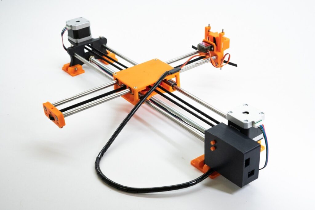
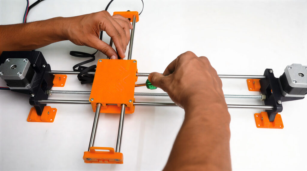
I built the frame and structural mounts using 3D-printed components, which made it easy to iterate quickly and keep costs low. The motion system includes:
- X-Y axis linear motion with NEMA 17 stepper motors
- Linear rods with LM8UU bearings for smooth movement
- Servo-actuated pen lift mechanism
Electronics and Hardware
Main components:
- Arduino UNO with CNC Shield V3.0
- NEMA 17 stepper motors with A4988 drivers
- ESP32 Wi-Fi module for remote control
- Mini servo motor for pen lift
- 12V power supply
- Linear bearings and guide rods
Adding Wi-Fi Control
Out of the box, GRBL machines are controlled over a wired USB connection. I added an ESP32 between the network and the Arduino. The ESP32 receives G-code jobs over Wi-Fi and forwards them to the Arduino via serial. Telemetry flows back the other way in real time.
This gave the plotter capabilities it didn't have before:
- Wireless G-code transmission from any device on the network
- Browser-based interface for start, pause, and stop
- Live job progress and motor state monitoring
- Remote calibration and test routines
- Job completion and error notifications
Software Workflow
Designs were created in Inkscape, converted to G-code, and sent to the controller via Universal Gcode Sender or the wireless interface. I also wrote Python scripts to handle serial communication, automate calibration routines, and log telemetry during development.
# Serial communication with Arduino (GRBL)
import serial, time

ser = serial.Serial('/dev/ttyUSB0', 115200, timeout=1)
time.sleep(2)  # wait for GRBL init

def send_gcode(cmd):
    ser.write((cmd + '\n').encode())
    return ser.readline().decode().strip()

print(send_gcode('$H'))           # home
print(send_gcode('G0 X50 Y50 F1000'))  # move
Working Principle
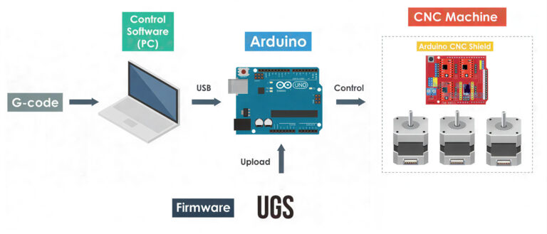
A digital design is processed in Inkscape and exported as G-code. That G-code is sent either over USB or wirelessly through the ESP32. The Arduino running GRBL interprets the commands and drives the stepper motors, moving the X and Y axes while the pen mechanism draws on the surface. The IoT module monitors execution and sends live status back to the control interface.
Demo
What I Learned
- GRBL is deceptively configurable. Most early calibration work came down to tuning step/mm values and acceleration limits, not code.
- 3D printing speeds up iteration. Being able to print a new mount overnight and test it the next day made the mechanical side much faster to develop.
- Serial communication is simple but fragile. The ESP32-to-Arduino bridge worked well once baud rates and buffer handling were right, but it took real debugging to get there.
- IoT adds failure surface area. Adding network connectivity means adding a new failure mode. Handling disconnects and job interruptions gracefully took more thought than the happy path.